Techniques and analytical methods
The IAC hosts a wide range of advanced materials science analysis techniques. Please contact us for more information. In addition to conducting materials science research we also perform analysis and consultancy services to industry.
Microscopy
Instruments available
- EDAX Velocity Pro EBSD detector mounted on the Zeiss Sigma HD VP Field Emission SEM.
- Oxford Instruments Symmetry S2 EBSD mounted on the FEI Helios Hydra Plasma FIB.
- Oxford Instruments Symmetry S2 EBSD mounted on the FEI Helios Nanolab 600 FIB.
Principles
To use EBSD a beam of electrons is fired on the point of interest of a crystalline sample, which is tilted at approximately 70° to the normal incidence of the electron beam in the SEM; this is to increase the contrast in the diffraction pattern and the fraction of the electrons scattered from the sample. When the electron beam interacts with the sample, at an angle which satisfies Bragg’s equation, the electrons scatter inelastically to form a pair of cones of diffracted electrons.
Typical applications & limitations
- Sample preparation can be a lengthy process.
- Sample size needs to fit into instrument at 70° tilt.
- How much the specimen is tilted is a trade off between how much the sample is exposed and the image quality, with image quality increasing at greater tilt and exposure decreasing.
- The patterns come from the top 7-10nm of the material.
- Provides high resolution data of the sample surface; the smallest step-size achievable is ~15nm.
- Non-conducting samples (rocks, etc.) can be studied in Variable Pressure mode within the Zeiss Sigma VP SEM.
- Can be conducted simultaneously with EDX analysis to provide composition data.
Instruments available
- FEI Helios NanoLab 600 with Kleindeick micromanipulator, Oxford Inst X-Max50 EDS, Oxford Instruments Symmetry S2 EBSD detectors, platinum deposition and force measurement.
- ThermoFisher Hydra Plasma FIB with Xe, O, Ar and N plasma ion beams, Oxford Instruments UltimMax EDS and Symmetry S2 EBSD detectors, Easylift micromanipulator, W, Pt, C, XeF2, SiO2, I, Au and H2O gas injection system, cryogenic stage and vacuum transfer system.
- ThermoFisher Scios 2 Gallium FIB with ThermoFisher EDS detector, Easylift micromanipulator, W, Pt, C, and XeF2 gas injection system.
Principles
FIB systems are similar to SEMs but instead of electron guns use a focused beam of gallium ions; by using a low beam current they can be used for imaging and with a higher beam current for site specific sputtering or milling. Sputtering is a process where an atom is ejected from the surface of a sample as it’s bombarded by the high energy particles.
As the ion beam passes over the surface it sputters ions, and produces secondary electrons. The signals from both of these are used to create an image. At low beams the images are useful for looking at grain orientation contrast, morphology and boundary contrasts.
FIBs are typically used for semiconductor fabrication; used for defect analysis, circuit modification, mask repair and TEM slide preparation. They can also be used to deposit materials, for example, to deposit a conductive material. A further use of FIBs is to analyse the secondary ions produced with mass spectroscopy to identify chemical compositions.
FIBs can also use samples which have been cryogenically frozen, so don’t necessarily have to be solid.
Typical applications & limitations
- Used in the preparation of sections for STEM, TEM and atom probe study.
- Samples studied are typically electrically conductive, if the sample is non-conductive however - a low energy flood gun or conductive coat such as gold or carbon can be used to provide sample neutralisation.
- This method is inherently sample destructive; sputtering and implantation of gallium ions create an amorphous surface.
- Surfaces are roughened by sputtering at the sub-micrometre scale.
- Our new plasma focused ion beam instrument uses Xe, Ar, O and N plasmas instead of gallium, and is capable of milling at much faster rates for large-scale 3D slice-and-view cross-sections including with EBSD and EDX imaging of each slice.
Instruments available
- Bristol Nanodynamics dynamic SPM (HS-AFM), a custom-built scanning probe microscope, operating in high-speed contact mode.
- Bristol Nanodynamics HS-AFM in dedicated environmental and shielded container, operating in high-speed contact mode.
Principles
Making use of newly-discovered physics, our contact mode high-speed atomic force microscope (HS-AFM) is the fastest in the world by several orders of magnitude. The HS-AFM moves the sample in a raster pattern and engages a sharp tip with the surface to map sample topography with nanometre lateral and sub-atomic height resolution over millimetre-sized areas. The tip can be thought of as a finger passing across a surface, able to map both the height of the surface and the local stiffness, thermal and electrical properties at the same time. The microscope doesn't require either the sample to be conductive or a vacuum to operate; indeed, it is able to image samples in gaseous and liquid environments.
Typical applications & limitations
The HS-AFM typically collects data at 2 million pixels per second. However, this can be increased to 10 million pixels per second if required. These rates allow the HS-AFM to image millimetre-sized areas in under a day, a task that would take a conventional AFM in excess of a year. Examples include: vast sampling of nanostructures for unbeatable statistics and measurement certainty; and mapping of nano-structures across large areas. The high pixel rate can also be used to observe nano- and micro-scale dynamic processes with millisecond temporal resolution, e.g. metallic surface corrosion, crystal/salt formation and bio-molecular processes.
Sample preparation
As the HS-AFM physically moves the sample to build up an image the sample should be kept below 300g mass and under 2 x 2cm in size. If large areas are to be imaged then it is important that the bottom and top surfaces are parallel to minimise any slope. As with any scanning probe microscope it is important that the structures to be imaged are not mobile. We have found that if the sample can be imaged with a standard AFM then we are able to image it using the HS-AFM.
Instruments available
- Leica GZ6 stereo zoom optical microscope (reflected light microscopy).
- Nikon Metaphot compound optical microscope (reflected and transmitted light microscopy).
- Olympus BH2 compound optical microscope with colour CCD camera and computer for image acquisition (reflected and transmitted light microscopy).
- Olympus BX60 compound optical microscope with CCD camera and computer for image acquisition (reflected and transmitted light microscopy).
- Olympus SZ11 stereo zoom optical microscope with colour CCD camera and computer for image acquisition (reflected light microscopy).
- Zeiss Axioscope 7 compound optical microscope with colour CCD camera and computer for image acquisition (reflected light microscopy).
Principles
The optical microscope uses a lens, or converging mirror which creates a focal point for the light coming off the sample. More often a lens is used, and in modern microscopes with higher imaging power multiple lenses are used (a compound microscope).
A compound microscope magnifies an object by placing the sample on a stage, which is lit from below. The lens closest to the sample is the objective and the eyepiece (or ocular lens) is located at the opposite end of the microscope.
They are separated by the body tube. The objective lens is actually comprised of a number of different lenses, which work together to form the intermediate image, an enlarged version of the sample. The eyepiece then further magnifies the intermediate image, and is what a person will see.
Typical applications & limitations
- A finite resolving capacity of approximately 200nm, which limits magnification to approx. x1500.
- Sample may need preparation e.g. live cells to be stained and thin sections of rocks.
- Useful for an initial examination of a material prior to further analytical techniques.
Instruments available
- Zeiss Evo MA10 LaB6 SEM with EDAX EBSD and EDX.
- Zeiss Sigma HD VP Field Emission SEM with EDAX Velocity EBSD and Octane Elect EDX, backscattered electron and variable pressure detectors, three axis micromanipulator, cryogenic-can and in-situ Ar+ ion sputter cleaning.
Principles
The scanning electron microscope uses a focused beam of high energy electrons to create a signal at the surface of solid specimens. SEM machines can magnify in the order of 50 to 250,000 times, and generally cover an area from 1cm down to 500nm.
The emitted secondary electrons provide information on specimen morphology and topography; the angle of secondary electron emission is affected by the angle of incidence.
An important factor in SEM is the accelerating voltage of the primary electron beam; a greater accelerating voltage gives increased depth penetration. Greater depth penetration can be positive or negative, depending on the aim of the investigation. However, the accelerating voltage also causes a greater interaction volume, thereby decreasing the control the SEM has of where signals are generated from.
SEMs often have secondary detectors which use some of the other signals generated to provide further information about the sample. Backscattered Electron Imaging (BEI) and Energy Dispersive X-ray (EDX) analysis are commonly used; these provide information on the atomic number of the sample and compositional information. Electron Backscattered Diffraction (EBSD) detectors generate information on the crystallographic orientation and phases present in the sample.
Typical applications & limitations
- Examination of samples not possible under light-microscopy.
- Can utilise analytical techniques (EDX and EBSD) in the SEM.
- EDX is unable to detect H, He, Li and Be elements.
- The sample must be solid.
- The sample must be able to fit into the microscope chamber.
However, some of these problems can be overcome using variable pressure mode within the Zeiss Sigma SEM.
Spectroscopy/Spectrometry
Instruments available
- Renishaw System 100, 514nm green laser with standard and micro probes (spot Raman analysis of large and in-situ components, for example alumina- and zirconia-based oxides on turbine surfaces).
- Renishaw System 2000 micro-Raman imaging spectrometer, 632.8nm red and 514nm green lasers, with integral Leica compound optical microscope (micro Raman analysis of materials, spot analysis and mapping).
Principles
Raman spectroscopy is a type of vibration spectroscopy which can look at molecular motion and fingerprint species. A beam of photons is aimed at the sample, which excites a molecule. As the molecule loses the energy a photon is emitted.
Most photons are elastically scattered (Rayleigh scattering) so the scattered photons have the same energy as the incident photons, but some are inelastically scattered (Raman scattering) so that they have a different frequency, usually lower, than the incident photons.
This energy shift (Raman shift) gives information about the vibrational modes in the system.The output (below) shows the intensity versus the Raman shift (in wave numbers), it is also the inverse of IR spectroscopy. The peaks can be identified as different bonds in molecules.
Typical applications & limitations
A difficulty in LRS is that Raman scattering is typically weak, so to separate the weak Raman scattered light from the strong Rayleigh light requires special detectors.
- While LRS can be used for solids and liquids it cannot be used for metal alloys.
- Fluorescence of impurities or of the sample itself can hide the Raman spectrum.
- Sample heating through laser radiation can destroy the sample or cover the Raman spectrum.
- Limited sample preparation is required when using LRS.
Instruments available
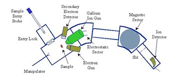
- IAC magnetic sector SIMS/ion milling instrument.
Principles
A SIMS uses an ion beam to sputter the surface of a sample, then analyses the secondary ions which are ejected. SIMS has a low detection limit, with some instruments being able to detect samples in the parts per billion range.
A schematic of a SIMS is shown below, a large part of the machine acts as a conventional mass spectrometer. It uses an electromagnet which will deflect more charged ions a greater amount than less charged ions, and heavier ions less than lighter ions.
SIMS also use quadrupole mass analysers which separate ions based on their resonant electron field, this allows only selected masses to pass through. Another means of sample identification is “time of flight”, the velocity of the ions are measured and as the ions all have the same kinetic energy, the only factor affecting the velocity is the mass.
Typical applications & limitations
- Can be used on a wide range of materials, sampling the upper-most layers.
- The sample must be stable in a vacuum.
- The sample will be degraded by sputtering process.
- The ions from the primary beam could be included in the mass spectrum.
Instruments available
- Specs x-ray photoemission system with x-ray photoelectron, ultraviolet photoelectron and Auger electron spectroscopy, vacuum transfer capability and enhanced depth profiling.
- Links to the Bristol NanoESCA facility for angle-resolved ultraviolet photoemission spectroscopy and photoelectron emission microscopy (PEEM).
Principles
The sample is irradiated with a beam of x-rays, which excites an inner shell electron.There are two principal types of x-rays used, monochromatic aluminium Kα x-rays (monochromatic x-rays only have a single wavelength or a narrow band) and non-monochromatic x-rays. These x-rays have a known wavelength which corresponds to a known photon energy (Ephoton).
Typical applications & limitations
- An inability to detect elements with an atomic number below 3 (hydrogen and helium).
- The ultimate detection limit is around 100ppm for most elements.
- Is surface sensitive, measuring the top 10-12nm of material.
- Non-monochromatic x-rays produce heat, and Bremsstraglung x-rays can degrade the surface.
- The binding energies may need to be charge-corrected if the surface has a charge deficit or surplus.
Other
Instruments available
- Quantachrome NOVA 1200.
Principles
The principal behind BET uses the assumption that if a gas is absorbed onto the surface of a powder, it will be absorbed on a layer a single atom thick. The principle behind the technique relies on the fact that a more stable energy state is reached when every atom/molecule is surrounded by neighbours.
The gases usually used are nitrogen and krypton, so by measuring the volume of gas absorbed the surface area can be determined by some simple calculations. By some additional calculations data on mean pore size and pore size distribution can be determined.
Typical applications & limitations
This technique produces challenges in that different materials have different absorption characteristics. For example types III and V are not compatible with the BET method because there are only weak interactions between the solid and gas.
The sample also requires some preparation to remove impurities which are physically bonded to the surface, this is usually done by raising the temperature while in a vacuum or surrounded by an inert gas.
Instruments available
- Mettler Toledo TGA/DSC1 Star System.
Principles
A DSC consists of the sample and a reference, the temperature of the surroundings of both is raised equally and the difference in intrinsic temperature of the sample and reference are measured.
DSCs are commonly used to find the temperature at which phase transitions occur, e.g. solid to liquid, and whether these reactions are exothermic or endothermic (heat releasing or heat using) and the specific heat capacity of a sample.
The output of these techniques gives the temperature against the heat flow or against heat capacity.
Typical applications & limitations
- Unsuitable for two phase mixtures.
- Difficult to prepare samples which are volatile solvents.
- Doesn't detect gas generation.
Principles
DC Magnetron Sputtering is a physical vapour deposition technique which is predominately applied to the creation of thin film samples of conductive materials.
At Bristol using a UHV set-up reaching 10-10mbar vacuum gives the opportunity to produce incredibly clean samples with the only impurities dependent on the target material.
With a large range of substrate materials and in-situ heating available during growth, there is the opportunity to produce epitaxial films yielding single crystal samples.
The current set-up allows for up to four target materials to be used at any one time for sample creation. This in the past has been utilised to produce alloys, compounds and multi-layers for a number of applications.
One other option for more advanced sample production is via reactive sputtering (with a partial pressure of 2x10⁻⁵mbar), which has been used in Bristol to produce oxides for a very fruitful programme of research.
Current projects lead by Dr Ross Springell are based around actinide thin film production, predominately uranium metal and oxides for fuel and metal storage research. However, we have a large range of different target materials currently available and most metallic elements are possible to procure.
For further information or to talk about possible projects please contact:
Dr Ross Springell phrss@bristol.ac.uk
Instruments available
- Mettler Toledo TGA/DSC1 Star System.
Principles
The principal of TGA is to use a precision balance and a programmable furnace to measure mass change, temperature and temperature change. The instrument continually weighs a sample while it is being heated up to temperatures of 2000°C.
The output with this method shows temperature on the x-axis and mass loss on the y-axis. To avoid contamination of the sample, as it is heated the chamber should be purged with an inert gas, which will not react with the sample.
TGA is often combined with a gas analysis instrument; they use infrared spectroscopy, mass spectrometry and gas chromatography, which aid in sample identification and quantification.
Typical applications & limitations
- Sample is destroyed.
- Only a minimal amount of sample is required (varies depending on machine).
- Solid samples only.
- Data interpretation can be complex.
Instruments available
- Philips X'pert X-ray diffraction system.
- Rigaku SmartLab SE X-ray diffraction system.
Principles
XRD works by directing x-rays onto the surface of a sample. The distribution of atoms across planes in a crystal lattice causes incident beams of x-rays to interfere with one another as they leave the crystal. The output of an XRD analysis gives the intensity of the diffracted x-ray signal as a function of incidence angle, 2θ. By using Bragg's law, nλ=2dsinθ, where:
- d=distance between lattice layers.
- λ=wavelength.
- θ=angle if incidence.
distances between lattice layers can be determined and compared to database of reference patterns. Thus, the composition of a specimen can be investigated.
Using our x-ray diffractometers, we can provide you with information on the sub-nanometer length-scale. We are able to investigate powders, polycrystalline samples, single crystals and even thin films. We have hot stages that can heat to 1200K and a cryostage that can reach liquid nitrogen temperatures - these can be used in combination with high vacuum or a controlled gas atmospheres.
Limitations
- Measurement depths are generally quite shallow, less than 30 microns.
- Only applicable to crystalline materials.
- The accuracy is detrimentally affected by grain size and texture.
- Samples need a good surface finish so delicate preparations my be necessary.

Instruments available
- Zeiss Xradia 520 Versa.
Principles
Spatial and temporal observations at nano and microscales are key to progressing world-class work led by the University of Bristol together with the University of Oxford and its GW4 partners into all manner of material challenges.
A Zeiss Xradia 520 Versa x-ray tomography (XRT) instrument, able to observe in-situ experiments on a scale previously reserved for synchrotron work and the capability to work with radioactive materials, is opening up fields of research that are of great interest to academia and industry at a level that returns the UK to the international top table of materials research.
Advanced x-ray tomography works by illuminating a specimen with a known x-ray energy, imaging the transmission through 180° or 360° and reconstructing the data to give a truly 4D representation of a material with internal and external feature development throughout in-situ testing. Instrumentation of this capability is of interest to a multitude of fields of research, the support for which is being managed by the University of Bristol Interface Analysis Centre, a regional materials analysis hub with a strong track record and experience in providing cutting-edge analysis for a multitude of different academic and industrial groups.
Typical applications & limitations
- Non-destructive 3D or 4D microscopy of specimens.
- Little or no sample preparation required.
- Features may have insufficient attenuation contrast for useful imaging.
- Image artifacts (eg beam hardening) may complicate data acquisition and interpretation.
For further information or to talk about possible projects please contact:
Dr Chris Jones cj0810@bristol.ac.uk