Coup2D
Contact: Katerina Michaelides
The model Coup2D (Michaelides, 2000) was developed to investigate the process of hydrological connectivity and hillslope-channel coupling of surface runoff in semi-arid catchments (< 100 km2) during single rainfall events. Coup2D is being used a heuristic tool for investigating uncertainties associated with varying connectivity in spatial patterns in surface properties, topography and rainfall.
Model Processes
Coup2D incorporates the dynamic hydrologic interactions between hillslopes, floodplains and channel belt, thus accounting for different degrees of coupling between hillslopes and channels (figure 1). The main unique features of Coup2D are:
- The integration of hillslope, floodplain and channel hydrology and hydraulics;
- The dynamic interaction between channels and hillslopes and floodplains and hillslopes in terms of runoff; and
- The simultaneous routing of hillslope- and floodplain-overland flow and channel flow.
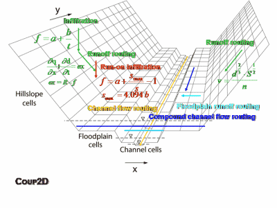
Figure 1: Processes in Coup2D
Topographic Structure
Coup2D combines a grid-based representation of the hillslope elements and a channel represented by a series of cross-sections. Hillslopes and floodplains are represented by a two-dimensional digital elevation model (DEM), while the channel and floodplain (during overbank conditions) are represented by a series of one-dimensional cross sections (figure 2).
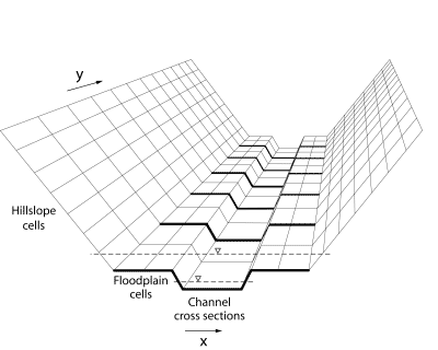
Figure 2: Topographic structure of Coup2D
Infiltration
In Coup2D infiltration is described by the modified Green and Ampt (1911) equation which predicts the time to runoff and the decline in infiltration rate as a result of filling a fixed soil-moisture store:
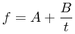
Equation 1: Green and Ampt infiltration
where f is the infiltration rate (m s -1), A is the final infiltration rate under saturated conditions (m s -1), B is the initial infiltration rate under unsaturated conditions (m) and t is time (s).
Runon Infiltration
Runon infiltration (or reinfiltration), whereby water flowing off the slopes and floodplains is allowed to infiltrate into areas where the soil-moisture storage capacity has not reached the maximum, is also represented in Coup2D. The representation of runon gives more meaning to the infiltration parameters assigned to each element and to the spatial patterns of infiltration rate over the catchment and is, therefore, more likely to produce more realistic results of runoff. The process of runon infiltration is simulated in Coup2D using the approach of Wainwright and Parsons (2002). Equation (1) has been modified to replace the time component with the cumulative stored water in the soil. The modified equation is:
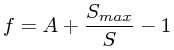
Equation 2: Runon infiltration equation
where S max is the total available soil-water storage (mm) and S is the current cumulated depth of water stored in the soil profile (mm). The value of S maxis estimated from A and B and by calculating the definite integral of equation (1) for the time taken to reach saturation, assumed to be 60 minutes. This gives the following relationship:
![]()
Equation 3: Smax
At each time step, the process of runon infiltration is simulated by calculating the depth of water on a cell as the sum of the existing flow depth and the current rainfall intensity. If the infiltration rate from equation (2) exceeds this value, then both the surface water and the rain are re-infiltrated. If the infiltration rate is greater than the total water depth and less than the rainfall rate, then the amount of runon infiltration occurring is taken as their difference. Finally, if the infiltration rate is less than the rainfall rate, runon infiltration is assumed not to occur and, therefore, rainfall excess is calculated at each time-step as the difference between the rainfall intensity and the infiltration rate.
Runoff Routing
Overland flow is routed using the kinematic wave approximation rated using the Manning's n friction factor, with flow routing from cell to cell defined by a steepest descent algorithm. Rainfall excess from the hillslopes, qh (m s-1), is incorporated with surface flow using the continuity equation to produce the kinematic wave approximation to the Saint Venant equations for overland-flow routing on the hillslopes and floodplains:
Equation 4: Kinematic wave equation
where q is water discharge per unit width (m2 s-1), d is flow depth (m), x is distance (m) and t is time (s). The overland-flow routing component uses an explicit (Euler) backward finite difference solution to the kinematic wave equation for the spatial and temporal prediction of flow depth.
Flow velocities are determined from Manning's equation:
Equation 5: Manning's equation
where v is velocity (m s-1), d is flow depth (m), S is channel-bed slope (m m-1) and n is Manning's roughness coefficient (m-1/3s). On the hillslopes, mean flow depth is used as an approximation of the hydraulic radius because the flow width is significantly larger than the flow depth. Velocity is then used in the rating equation (6) for continuity:
![]()
Equation 6: Rating equation
Lateral movement of water in the subsurface (subsurface stormflow) and saturation of the soil surface due to rising water tables (return flow) are assumed not to occur or to be relatively unimportant in semi-arid catchments, especially during short-term flood events (Michaud and Sorooshian, 1994), and therefore are not represented in this model version.
Channel-flow routing is described by the kinematic wave approximation:
Equation 7: Kinematic wave equation for channel routing
where qc is water discharge per unit channel width (m2 s-1), dc is flow depth of main channel (m) and qlat is lateral inflow to main channel (m) derived from the combined inflow from the two lateral hillslopes and floodplains. As with the hillslope- and floodplain- overland-flow routing, the kinematic wave formulation is solved by an explicit backward finite difference method. Channel-flow velocities are determined from Manning's equation (5) and velocity is then used as in equation (6) for continuity.
Papers on Coup2D
Michaelides, K. (2000) The effects of hillslope-channel coupling on catchment hydrological response in Mediterranean areas. Unpublished PhD Thesis, University of London.
Michaelides, K. and Wainwright, J. (2002) Modelling the effects of hillslope-channel coupling on catchment hydrological response. Earth Surface Processes and Landforms 27: 1441-1457.
Michaelides, K. and Wainwright, J. (2004) Modelling Fluvial Processes and Interactions. In: Wainwright, J and Mulligan, M. (Eds.) Environmental Modelling: Finding Simplicity in Complexity, 123-142. J. Wiley & Sons Ltd., Chichester.
Michaelides, K. and Wilson, M.D. (2007) The uncertainty in predicted runoff due to patterns of spatially variable infiltration. Water Resources Research, 43, W02415, doi:10.1029/2006WR005039.
Michaelides, K. and Wainwright, J. (in press) Internal testing of a numerical model of hillslope-channel coupling using laboratory-flume experiments. Hydrological Processes.