Aerodynamic optimisation
Staff:
Introduction
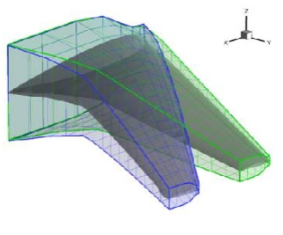
Aerodynamic shape optimisation using CFD requires a method to parameterise the surface, a method to deform the surface and computational fluid dynamics (CFD) volume mesh related to the chosen shape control parameters, a method to obtain the sensitivity of an objective function to each parameter, and a method to use these sensitivities to improve the design. Universal global interpolation and control methods have been developed (see also under mesh deformation) using radial basis function approximation, and linked to an efficient domain element approach. Changes to the domain element parameters are linked directly to the design surface and CFD volume mesh, to ensure accurate and smooth deformations. Figure right shows an example domain element parameterisation of a rotor blade, with a local twist parameter perturbation.
The sensitivity of the objective function, normally drag for a fixed wing case and torque for a rotor case, with respect to each parameter perturbation is obtained via a finite-difference approach, and these sensitivities are fed into a very effective FSQP optimisation method. This has also been parallelised, in a data sense, so that each parameter sensitivity can be computed independently on a separate processor, i.e. for 20 parameters 20 processors could be used, meaning all sensitivities are computed simultaneously.
MDO wing
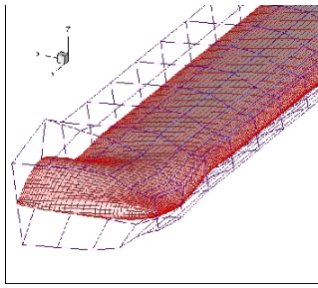
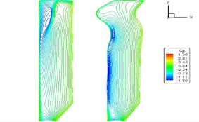
Figure (right) shows the initial and optimised MDO (Multi Disciplinary Optimisation) wing surface and domain element. This is a Mach 0.88 case, and the CFD code used was that of Allen. Figures below show the surface pressure coefficient contours, showing the elimination of the transonic flow in the optimised wing. The drag was reduced by 18%.
Rotor case
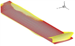
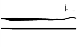
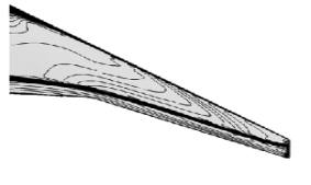
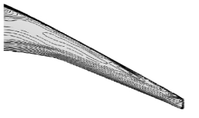
Figure (below: left, centre) shows the initial and optimised rotor surfaces, for a two-bladed rotor in hover. In this case the tip Mach number is 0.794, and again the CFD code used was that of Allen. Figure (below: right) that shows the surface pressure coefficient contours, showing the reduction in the transonic region on the optimised rotor, as a result of the surface deformation. The torque was reduced by over 25%.